Posts

2N2222 transistor datasheet pinout

Image
2N2222 transistor Datasheet   pinout   2N2222 NPN Transistor Datasheet, pinout, features and more   **General Description:**  The 2N2222 is an NPN bipolar junction transistor designed for general-purpose amplification and switching applications. It is commonly used in a wide range of electronic circuits due to its versatility and reliability.  **Features:**  - NPN silicon transistor  - Low power, high gain  - Collector current (IC): 800mA  - Collector-base voltage (VCBO): 75V  - Collector-emitter voltage (VCEO): 40V  - Emitter-base voltage (VEBO): 6V  - Transition frequency (ft): 250 MHz (typical)  - Low noise and distortion  - TO-92 package for easy mounting  **Pin Configuration:**  - Collector (C)  - Base (B)  - Emitter (E)  **Absolute Maximum Ratings:**  - Collector-base voltage (VCBO): 75V  - Collector-emitter voltage (VCEO): 40V  - Emitter-base voltage (VEBO): 6V  - Collector current (IC): 800mA  - Collector power dissipation (PC): 500mW  - Junction temperature (TJ): 200°C  - Stor

Power factor calculator

Image
What Is Power Factor? Power factor is a measurement that tells us how effectively electrical power is being converted into useful work output. In simple terms, it represents the ratio of real power (in watts) to apparent power (in volt-amperes) in an electrical system. Real power does the actual work, such as lighting a bulb or driving a motor, while apparent power accounts for both real power and reactive power, which doesn't perform any useful work but is required to maintain voltage levels. Power Factor Calculator Power Factor Calculator Real Power (Watts): Apparent Power (VA): Calculate Power Factor How to Calculate Power Factor To calculate power factor, you can use a simple power factor calculator or use the following formula: Measure the real power (in watts) being used by your system. This can often be found on your elec

BC107 transistor Datasheet and pinout

Image
Features: NPN Silicon Epitaxial Planar Transistor for switching and AF amplifier applications. Suitable for a wide range of applications such as amplification and switching. Complementary PNP type: BC177. Low collector-emitter saturation voltage. Absolute Maximum Ratings: Electrical Characteristics: (T_A = 25°C, unless otherwise specified) Pinout: Package Information: The BC107 transistor is typically available in a TO-18 metal can package. Applications: Amplification of weak signals. Switching applications in digital circuits. General-purpose NPN transistor for various electronic applications.

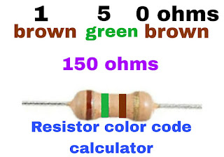
Resistor color code calculator

Image
अवरोध  इलेक्ट्रॉनिक्स की आकर्षक दुनिया में आपका स्वागत है, जहां हर घटक उन उपकरणों को शक्ति देने में महत्वपूर्ण भूमिका निभाता है जिन पर हम रोज भरोसा करते हैं। इलेक्ट्रॉनिक्स में नामांकित से एक अवरोधक है, जो विद्युत धारा के प्रवाह को सीमित करता है। उनकी विचारधारा को इंगित करने के लिए, हम एक प्रतिरोध रंग कोड का उपयोग करते हैं। इस व्यापक मार्गदर्शिका में, हम प्रतिरोध रंग कोड प्रणाली को तोड़ेंगे, सैद्धांतिक कि यह कैसे काम करता है, और आपकी सुविधा के लिए एक आसान टूल टूल प्रदान करता है। आओ, प्रतिरोधियों को संकेत दें कि इस यात्रा को एक साथ शुरू करें! अध्याय 1: प्रतिरोधों को बढ़ावा इससे पहले कि हम रेसिस्टर कलर कोड को डिकोड करने में उतरें, आइए इलेक्ट्रॉनिक सर्किट में रेसिस्टर्स के महत्वपूर्ण को पहचानें। निष्क्रिय घटक जो विद्युत धारा के प्रवाह को सीमित करते हैं। उनमें अलग-अलग परतें और आकार आते हैं, प्रत्येक का एक विशिष्ट प्रतिरोध मान होता है। इन मान सर्किट को डिज़ाइन करना महत्वपूर्ण है, यह सुनिश्चित करना है कि वे सही ढंग से काम करें। अध्याय 2: प्रतिरोध रंग कोड प्रतिरोध रंग कोड एक शानदार

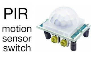
motion sensor switch circuit diagram

Image
रोशनी क्षमता:  मोशन सेंसर स्विच की शक्ति परिचय आज की तेज़-तर्रार दुनिया में सुविधा और दक्षता हमारे दिमाग में सबसे आगे हैं। एक क्षेत्र जहां इन सिद्धांतों ने महत्वपूर्ण प्रगति की है वह गृह स्वचालन और ऊर्जा संरक्षण का क्षेत्र है। मोशन सेंसर स्विच, जिन्हें अक्सर नजरअंदाज कर दिया जाता है, लेकिन अविश्वसनीय रूप से बहुमुखी हैं, ने प्रकाश प्रणालियों के साथ हमारे बातचीत करने के तरीके में चुपचाप क्रांति ला दी है। इस ब्लॉग पोस्ट में, हम मोशन सेंसर स्विच के चमत्कारों का पता लगाएंगे, उनके असंख्य लाभों, अनुप्रयोगों और हमारे घरों और व्यवसायों के लिए उनके उज्ज्वल भविष्य पर प्रकाश डालेंगे। मोशन सेंसर स्विच को समझना उनके फायदों के बारे में जानने से पहले, आइए मोशन सेंसर स्विच को स्पष्ट करें। इन बुद्धिमान उपकरणों को एक परिभाषित क्षेत्र के भीतर गति का पता लगाने और रोशनी को स्वचालित रूप से चालू या बंद करके प्रतिक्रिया देने के लिए डिज़ाइन किया गया है। वे एक साधारण आधार पर काम करते हैं: यदि कमरे में कोई नहीं है, तो ऊर्जा

Simple inverter circuit diagram using transistor 2sc5200

Image
 In today's world, where electricity is a fundamental necessity, power outages can be inconvenient and sometimes even life-threatening. The presented circuit diagram is designed to act as a simple inverter.  Very few electrical components have been used in this circuit.   This circuit is built using a transistor 2sc 5200 and a 12V stepdown transformer.  In addition, a resistance 1K Ohm and a ceramic capacitor 472J have also been used in this circuit.   The main feature of this circuit is that it consumes very little current.  This circuit requires a 4v to 12v DC supply to function.  This inverter can be easily made at home. Simple inverter circuit diagram  Note: Ensure that you follow safety precautions and take necessary measures when working with electricity. Disconnect the electric.  Safety Tips Always work in Double-check your connections and polarities before applying power. Use appropriate safety gear, like safety glasses and insulated tools. Keep

what is resistor

Image
 register is an electrical component used to reduce the electrical current in a circuit. The register is measured in units of ohms and has two terminals.  The register is constructed using carbon or metal wire. There are mainly two types of registers, fixed value registers, variable registers.  Fixed value resistors,  The value of fixed value register is always fixed, its value cannot be increased or decreased whereas the value of variable register can be increased or decreased.  Resistor Color Code Calculator Resistor Color Code Calculator Select the colors of the bands on your resistor: Band 1: Black Brown Red Yellow Green Blue Violet Grey White Band 2: Black Brown Red Oregon Yellow Green Blue Violet Grey White Band 3:

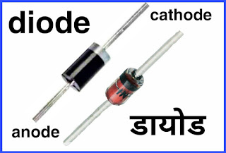
what is diode

Image
  Diode  Diode is an electrical component. Its full name is Semiconductor Diode Valve. The diode was discovered in the 19th century by a scientist named Thomas Edison.  Diodes are made of germanic silicon semiconductor. There are many types of diodes, but most of them have two ends, one anode and the other cathode.  Speciality  The main feature of diodes is that they allow current to flow in only one direction with low resistance. While they do not allow the electric current to flow in the opposite direction, due to this feature, they convert AC (alternating current) to DC (direct current).  Watch video  Main work  Diode is the most commonly used electrical component. Diodes are mainly used to convert AC current into DC current. Apart from this, diodes are used in battery chargers, inverters and all electrical equipment running on DC current. Symbol  The diagram below shows the symbol used in the circuit diagram of a

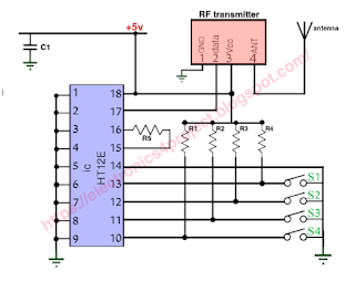
rf remote control circuit diagram

Image
 Presented circuit diagram is of RF remote control switch.  This remote control switch allows up to four electrical appliances to be turned on and off.   The biggest feature of the RF remote control switch is that it does not traditionally require the remote to be placed in front of the appliance to turn it on or off as it works on RF frequency. The radio frequency ranges from 30 KHz to 300 MHz. RF module ASK modulation is used in this system.  ASK modulation (Aptitude Shift Keying).  Radio frequency remote is better than ir remote because the range of RF remote is much better than ir remote.  The range of RF remote is about 30 to 100 meters. You can use this remote from any corner of the house.  With this remote control, you can turn on/off electrical appliances from any corner of the house.   This project is divided into two section transmitter circuit and receiver circuit.   Rf transmitter circuit  The RF remote control transmitter secti

led bulb driver circuit diagram

Image
      Illuminating the Future:  Understanding LED Bulb Driver Circuit Diagrams Introduction In today's world, the lighting industry is undergoing a significant transformation with the widespread adoption of LED (Light Emitting Diode) technology. LED bulbs are energy-efficient, long-lasting, and environmentally friendly alternatives to traditional incandescent and fluorescent lighting. However, behind the simplicity of an LED bulb lies a complex LED driver circuit that plays a crucial role in ensuring optimal performance. In this blog post, we'll delve into the world of LED bulb driver circuit diagrams, demystifying their components and functionality to help you better understand these modern marvels. **Chapter 1: The Basics of LED Technology** Before we dive into LED driver circuit diagrams, let's establish a fundamental understanding of LED technology. LEDs are semiconductor devices that emit light when an electric current passes through