Posts

Showing posts from 2019

gas leak detector circuit diagram

Image
LPG has become the need of everyone these days.  Nowadays everyone is using gas cylinder to cook food, but just as the use of LPG is continuously spreading its feet, similarly the accident caused by gas cylinder cannot be ignored because during use of LPG Gas leaks often lead to accidents.  A gas leak detector is a useful project to prevent accidents due to LPG leaks.   Gas Leak Detector The gas sensor MQ2 installed in the project is sensitive to Hydrogen, LPG, Smoke and Alcohol.  This project can be used to prevent any accident by detecting gas leak in home, shop and industry. The presented project serves as a gas leak detector.  This circuit is designed using gas sensor and transistor BC 148 .   This circuit will notify you of gas leaks by sounding an alarm.  The list of electronic components used in this

Powerful electric chaser circuit diagram

Image
The presented circuit is used to make an electric changer. Many colorful bulbo can be added together with this changer.  This project can be used for decoration on any function or festival.  This project is very simple, durable and very low cost.  This circuit can be made very easily. This circuit is constructed using two NPN transistor BC 548 .  And to reduce or decrease the running speed of the light, a variable registers of 22k ohm have been used in this circuit. And used a diode 1N4007 to protect this circuit.  list of all the electronic components used in this circuit is given below. How to make electric chaser watch full video  Electronics components list  Transistor  Q1, Q2 BC548  Capacitor  C1 100uf 25v  C3 10uf 25v  C2 103pf Resistance  R1, R2 68k ohm  R3, R4 1.5k ohm  V/R1 22k ohm  Diode  D1 1N4007  LED 2p Relay 18v PCB B

variable running led lights circuit diagram

Image
Variable running led lights  The project presented is used for home decorations at Deepawali or other festivals.  This circuit is built using 2 ic LM555 and CD 4017.  And 8 different color LEDs have been used in this circuit. All the LEDs blinks one after the other, which looks very beautiful . And the list of all the components used in this circuit is given below. Circuit diagram  Electronics components list  ic 1 NE555  ic 2 CD4017  V/R 1  100k Resistance  R1 to R8 220 ohm  R9 10k Capacitor  C1 10uf 25v LED  LED 8P 5MM PCB BORD 3×2" Watch full video 

overheat protection circuit diagram

Image
The project is used to protect electrical equipment from over hits. By using this product, transformers, electric motors and other electrical equipment can be saved from burning due to over hits.  The project presented is designed using two ic LM35 and LM358. The ic LM35 has been used as a digital output temperature sensor. A 10k ohm variable resistor is used in this circuit to set at a suitable temperature.   As the temperature of ic LM 35 increases, plus voltage is started on its output pin number 2.  And its pin number 2 ic is connected to pin number 3 of LM358. Hence ic LM358 comes in on condition. And its output pin number one starts getting plus voltage. And pin number 1 of ic is connected to the base of transistor BC548 . Therefore, the plus boltage reaches the base of the transistor. And transistor BC548 turns on. This causes the relay connected to the transistor, to comes n

Variable disco lighting circuit diagram

Image
The project presented is for decoration of homes and temples on festivals like Deepavali. It uses LEDs of different types of colors, which spread different types of beautiful colors. This circuit is made using two NPN transistors BC547. The list of main components used in the circuit is given below. Electronics components list  LED LIGHTS  5MM 10 piecs, Transistor  BC547 2 piece, Condenser  C1 10uf 12v C2 100uf 12v Resistance  R1, R2 56k ohm R3, R4 100 ohm, Push button 1 piece,  PCB BORD 

touch switch alarm circuit diagram

Image
The presented circuit is used as a touch switch alarm.  You can make this circuit safe by connecting it to your locker.  After connecting this circuit to the vault, the alarm will sound whichever person touches the vault.  This circuit is built using IC NE 555.  To generate alarm sound, we have used NPN transistor BC548 and PNP transistor BEL188 in it.  The list of components used in it is given below. ic NE555  TRA Q1 BC548  Q2 BEL188 Resi  R1 - 1m  R2 -  220k R3 - 10k V/R  100K Capacitor  C1 100uf 25v C2, C3  .01uf Diode  D1 1N4007  Speaker  PCB BORD Watch full video

mosquito repellent circuit diagram

Image
Mosquito Repellent Circuit Diagram  Keep Mosquitoes at Bay! Introduction: Mosquitoes are not just annoying, but they can also pose a health risk by spreading diseases like malaria, dengue, and Zika virus. While there are various commercial mosquito repellent solutions available in the market, creating your own DIY mosquito repellent circuit can be a cost-effective and eco-friendly alternative. In this blog post, we'll guide you through the process of creating a simple yet effective mosquito repellent circuit diagram to help you enjoy mosquito-free evenings outdoors. .mosquito repellent circuit  Materials Needed: Before we dive into the circuit diagram, let's gather the necessary materials: 1. 555 Timer IC 2. 1kΩ Resistor 3. 10kΩ Variable Resistor 4. 0.01μF Ceramic Capacitor 5. 10 pf 6. 9V Battery 7. Battery Clip 8. Breadboard and Jumper Wires Circuit diagram: Instructions: 1. **555 Timer Configuration:**    - Connect Pin 1 (Groun

thief detector circuit diagram

Image
The presented circuit diagram is used to catch the thief.  This circuit is built using transistors BC548 and AC188.   Put a thin copper wire connected between the base and negative line of transistor BC548 where there is a way for thieves to enter the house.   Now as soon as the thief tries to enter the house, the copper wire will break and as soon as the copper wire breaks, the positive voltage through the resistance R1 10k will come to the base of transistor  BC 548 and the circuit will be turned on.   As soon as the circuit is turned on, the resistance and 103PF connected between the transistor BC548 base and the collector of transistor AC188 together produce a sairan-like frequency that will be heard in the speaker connected to the collector of transistor AC188.  This circuit is very simple and very easy to use. A list of electronics components used in this circuit given below.  Thief detector circuit diagram 

water tank motor auto on/off switch circuit diagram

Image
पानी की टंकी मोटर स्वचालित चालू / बंद स्विच  प्रस्तुत सर्किट द्वारा पानी की टंकी पूरी तरह से भर जाने के बाद टैंक की मोटर अपने आप बंद हो जाती है। और टंकी में पानी खाली होने पर मोटर अपने आप चलने लगती है।  इस परिपथ में IC 555 का प्रयोग किया जाता है। IC 555 इस सर्किट और टाइमर सर्किट दोनों में समान रूप से काम करता है। और IC सुरक्षा के लिए, हमने इसमें एक डायोड in4007 जोड़ा है। इसके अलावा इस सर्किट में 2 ट्रांजिस्टर BC548 का भी इस्तेमाल किया गया है। और एक रिले 18V का उपयोग ऑन-ऑफ स्विच के रूप में किया गया है। इस परियोजना में हमें तीन तारों को पानी की टंकी में विसर्जित करने की आवश्यकता है। +V तार को पानी की टंकी के सबसे निचले स्तर पर रखा जाना चाहिए और ic के ट्रिगर पिन 2 वाले तार को पानी की टंकी के मध्य स्तर पर रखा जाना चाहिए। और तीसरा तार जो ट्रांजिस्टर Q1 के आधार से जुड़ा है, पानी की टंकी के शीर्ष पर रखा गया है। काम करने का ढंग पानी की टंकी मोटर ऑटो चालू/बंद स्विच 

0v to 12v adjustable power supply

Image
0 to 12v adjustable power supply circuit diagram  From the output of the presented circuit, we can take a regulated output supply from 0 to 12 volts. This circuit is made using transistor bd139. And to control the output voltage, we have used a 10k variable register in this circuit.  The list of electronics components used in this circuit is given below. 0 to 12v adjustable power supply circuit diagram  0 to 12v adjustable power supply  Electronics components list  PCB BORD IC NE555 (1P) TRA BC 548 (2P) RESI 100 ohm (2P) 10 Kohm (1P) DIODE 1N4007 (1P) RELAY How to make 0 to 12v adjustable power supply Watch full video 

day-night on/off switch circuit diagram

Image
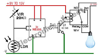
> Day night on/off switch circuit diagram  This circuit is built using timer IC 555.  It is a circuit running from 9 to 15 volts DC.  In this circuit, a 20K variable resistance is used to adjust the desired level of day and night.  And LDRs have been used as night and day sensors.  And a diode 1N4007 is used to protect ic from high voltage.   And it is also very easy to make and the list of components used in this circuit is given below. ic 555 Transistor  BC548 - 1p Resistance  100 ohm -1p V/R 20K ohm Diode  1N4007 - 1p LDR  RELAY 12V PCB BORD  Watch full video

Password lock circuit diagram

Image
Building a Secure Password Lock Circuit with IC CD4017: A Step-by-Step Guide Introduction: In today's digital age, security is of utmost importance. Whether it's your home, office, or personal belongings, safeguarding them with a reliable locking mechanism is essential. One effective way to enhance security is by creating a password-protected lock circuit. In this blog post, we will guide you through the process of building a secure password lock circuit using the versatile IC CD4017. **Table of Contents:** 1. **What is IC CD4017?** 2. **Components Required** 3. **Circuit Diagram** 4. **Circuit Explanation** 5. **Construction Steps** 6. **Testing the Password Lock Circuit** 7. **Enhancements and Customizations** 8. **Conclusion** **1. What is IC CD4017?** IC CD4017, also known as the Decade

what is mov

Image
 Title: Unveiling the Power of Metal Oxide Varistors (MOV): Guardians of Your Electronics Introduction In the world of electronics, where the steady flow of power is essential, Metal Oxide Varistors ( What is a A How Does The core principle behind MOVs is their Key Features and Adv Fast Response Time: MOVs react to voltage surges in nanoseconds, offering near-instant protection to connected devices. Wide Voltage Range: MOVs are available in a variety of voltage Reliability: These devices have a long lifespan and can handle Self-Healing: MOVs recover their high-resistance state after a surge Applications of MOVs Power Supplies: MOVs are commonly used in power supplies to protect sensitive electronics from voltage spikes originating from the power grid. The use of MOV in the cir

water tank motor automatic on off switch circuit diagram

Image
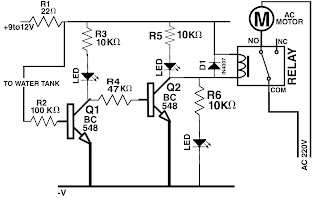
Water tank motor auto on/off switch  Presented circuit diagram is of automatic switch on off of water tank motor.   With the use of this circuit, the tank motor will automatically switch off as soon as the water tank is full.  But as soon as there is les little water in the tank, the tank-motor will be switch on automaticly.  This circuit diagram is especially for those people who want to keep their water tank full all the time. Water tank motor auto on/off switch circuit diagram  This circuit is made using two transistors bc548. And 18 volt relay has been used as a switch. 9 to 12 volt DC current is required for this circuit to work. How to make water tank motor auto on/off switch watch full video 

LED bulb circuit repairing video

Image
watch video

what is diode in hindi

Image
Diode  Demystifying Diodes: Understanding the Fundamental Electronics Component Introduction: When it comes to electronics, few components are as fundamental and versatile as the diode. Whether you're a seasoned engineer or just starting your journey into the world of electronics, understanding diodes is essential. In this blog post, we'll explore what a diode is, how it works, its various types, and its applications. So, let's dive into the world of diodes and shed light on this crucial electronic component. **Table of Contents:** 1. **What is a Diode?**    - Defining the Diode    - The Semiconductor Material 2. **How Does a Diode Work?**    - Understanding the P-N Junction    - Forward and Reverse Bias 3. **Types of Diodes**    - 3.1. **Rectifier Diodes**    - 3.2. **Zener Diodes**

transformerless power supply circuit diagram

Image
9 volt transformerless power supply  Presented circuit diagram is of 9V DC 200mA transformerless power supply.  A polyester capacitor C1 105J 400v is used in this circuit to step down the AC voltage.    Resistance R1 1mega ohm is used to discharge the capacitor. And resistance R2 10k Ohm 5w is used in this circuit.  Four diodes 1N4007 have been used in this circuit to convert AC volts to DC. Transformerless power supply circuit diagram  Apart from this, an electroletic capacitor C2 220UF 25v has been used in this circuit to filter the voltage.  A zener diode 9v 1W has been used in this circuit to protect the circuit.   This circuit is very simple and very easy to use.  The list of all the electrical components used in this circuit is given below. Electronics components list  polyester capacitor 104j 400v=1p zener diod

led bulb repairing

Image
LED bulb repairing very easy way watch video click here to