Posts

Showing posts from October, 2020

Sound detector switch circuit diagram

Image
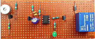
Sound detector switch    The presented circuit serves as the sound detector sensor.  This circuit is built using timer ic 555.   Sound detector switch circuit diagram  This circuit is turned on by any sound.  And automatically turns off after a few seconds.  The list of electrical components used in this circuit is given below. Electronics components list  ic NE555  Transistor  Q1, Q2, Q3 BC 547 Resistance  R1, 4.7Ik ohm R2, 1k ohm R3, 470 ohm R4, 47k ohm R5, 330 ohm Capacitor C1, C2, 0.1ufC3, 100uf          Mic condenser  Diode  D1, 1N4007  Relay 12v PCB BORD 

LED bulb simple driver circuit diagram

Image
LED bulb driver  The circuit presented is for the driver of 7 and 9 watt LED bulbs.  This circuit is designed using a 105J capacitor.   And a capacitor 474J has also been used to control the voltage of the circuit.  And one capacitor 47UF is used in this circuit to filter the voltage.   4 diodes 1N4OO7 have been used in this circuit to convert ac voltage to DC voltage.  A mov has also been used to protect the circuit.   The list of electrical components used in this circuit is given below. LED bulb driver circuit diagram    Electronics components list  Capacitor  C1 105j 400v C2 474j 250v C3 47uf 160v Resistance  R1 1m ohm Diode  1n4007 ×4 MOV 270V PCB BORD