Posts

Showing posts from March, 2021

fm transmitter circuit diagram

Image
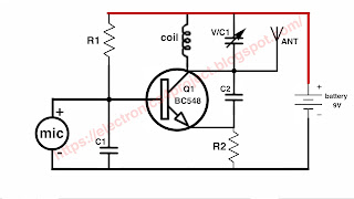
Building Your Own FM Transmitter:  A Step-by-Step Guide Introduction: In an era where wireless communication is king, understanding the basics of radio frequency (RF) technology can be both fascinating and practical. One exciting project to delve into this world is building your own FM transmitter. In this blog post, we'll provide you with a comprehensive guide, including a circuit diagram, to create your very own FM transmitter. Whether you're an electronics enthusiast or just curious about how it works, this DIY project is both educational and fun. **Chapter 1: Understanding the Basics of FM Transmitters** Before we dive into the circuit diagram and assembly, let's briefly explore what an FM transmitter is and how it works. 1. **What is an FM Transmitter?**    An FM transmitter is a device that can

transistor bc558 pinout

Image
 BC558 NPN Transistor pinout and Datasheet: Pinout: Collector (C) Base (B) Emitter (E) BC558 NPN Transistor Datasheet General Description:  The BC558 is a widely used NPN bipolar junction transistor (BJT) designed for general-purpose amplification and switching applications. It belongs to the BC54x series of transistors and is commonly used in low-power amplifier circuits, signal amplification, and as a switch in various electronic devices. Features: NPN transistor with three-layer construction. Low current (IC) and voltage (VCE) ratings. High current gain (hFE). Low saturation voltage. RoHS compliant. Electrical Characteristics (TA = 25°C unless otherwise specified): 1 Absolute Maximum Ratings: Collector-Base Voltage (VCBO): 30 V Collector-Emitter Voltage (VCEO): 30 V Emitter-Base Voltage (VEBO): 5 V Collector Current (IC): 100 mA Total Device Dissipation (PD): 500 mW Operating and Storage Junction Temperature Range (TJ,

high voltage generator circuit diagram

Image
 High voltage generator circuit diagram  The presented circuit diagram is designed to generete high voltage.  This circuit generates 2000 high volts dc. This circuit should be used very carefully.  This circuit is built using transistor D882.   This circuit is used to protect crops from wild animals and to protect them from monkeys.  And this circuit is also used in mosquito bat.  A list of all the electronic components used in this circuit is given below. How to make high voltage generator circuit watch full video  Electronics components list  Transistor  Q1 D882  Capacitor  C1 105j 400v C2 102 pf C3 101 of C4 223j 2000v  Diode  all diode 1N4007  LED light Resistance  R1 1m ohm  R2 18k ohm  R3 1.5I ohm  Transformer  L1 15 turn 0.2mm copper wire  L2 30 turn 0.2mm copper wire  L3 450 turn 0.05mm copper wire  Battery 4v PCB BORD