Posts

Showing posts from September, 2019

Variable disco lighting circuit diagram

Image
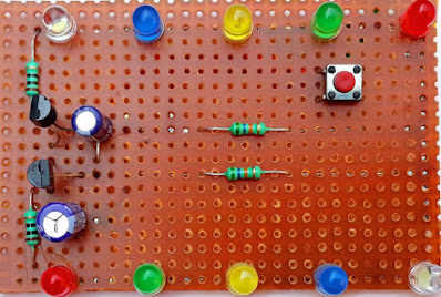
The project presented is for decoration of homes and temples on festivals like Deepavali. It uses LEDs of different types of colors, which spread different types of beautiful colors. This circuit is made using two NPN transistors BC547. The list of main components used in the circuit is given below. Electronics components list  LED LIGHTS  5MM 10 piecs, Transistor  BC547 2 piece, Condenser  C1 10uf 12v C2 100uf 12v Resistance  R1, R2 56k ohm R3, R4 100 ohm, Push button 1 piece,  PCB BORD 

touch switch alarm circuit diagram

Image
The presented circuit is used as a touch switch alarm.  You can make this circuit safe by connecting it to your locker.  After connecting this circuit to the vault, the alarm will sound whichever person touches the vault.  This circuit is built using IC NE 555.  To generate alarm sound, we have used NPN transistor BC548 and PNP transistor BEL188 in it.  The list of components used in it is given below. ic NE555  TRA Q1 BC548  Q2 BEL188 Resi  R1 - 1m  R2 -  220k R3 - 10k V/R  100K Capacitor  C1 100uf 25v C2, C3  .01uf Diode  D1 1N4007  Speaker  PCB BORD Watch full video

mosquito repellent circuit diagram

Image
Mosquito Repellent Circuit Diagram  Keep Mosquitoes at Bay! Introduction: Mosquitoes are not just annoying, but they can also pose a health risk by spreading diseases like malaria, dengue, and Zika virus. While there are various commercial mosquito repellent solutions available in the market, creating your own DIY mosquito repellent circuit can be a cost-effective and eco-friendly alternative. In this blog post, we'll guide you through the process of creating a simple yet effective mosquito repellent circuit diagram to help you enjoy mosquito-free evenings outdoors. .mosquito repellent circuit  Materials Needed: Before we dive into the circuit diagram, let's gather the necessary materials: 1. 555 Timer IC 2. 1kΩ Resistor 3. 10kΩ Variable Resistor 4. 0.01μF Ceramic Capacitor 5. 10 pf 6. 9V Battery 7. Battery Clip 8. Breadboard and Jumper Wires Circuit diagram: Instructions: 1. **555 Timer Configuration:**    - Connect Pin 1 (Groun

thief detector circuit diagram

Image
The presented circuit diagram is used to catch the thief.  This circuit is built using transistors BC548 and AC188.   Put a thin copper wire connected between the base and negative line of transistor BC548 where there is a way for thieves to enter the house.   Now as soon as the thief tries to enter the house, the copper wire will break and as soon as the copper wire breaks, the positive voltage through the resistance R1 10k will come to the base of transistor  BC 548 and the circuit will be turned on.   As soon as the circuit is turned on, the resistance and 103PF connected between the transistor BC548 base and the collector of transistor AC188 together produce a sairan-like frequency that will be heard in the speaker connected to the collector of transistor AC188.  This circuit is very simple and very easy to use. A list of electronics components used in this circuit given below.  Thief detector circuit diagram 

water tank motor auto on/off switch circuit diagram

Image
पानी की टंकी मोटर स्वचालित चालू / बंद स्विच  प्रस्तुत सर्किट द्वारा पानी की टंकी पूरी तरह से भर जाने के बाद टैंक की मोटर अपने आप बंद हो जाती है। और टंकी में पानी खाली होने पर मोटर अपने आप चलने लगती है।  इस परिपथ में IC 555 का प्रयोग किया जाता है। IC 555 इस सर्किट और टाइमर सर्किट दोनों में समान रूप से काम करता है। और IC सुरक्षा के लिए, हमने इसमें एक डायोड in4007 जोड़ा है। इसके अलावा इस सर्किट में 2 ट्रांजिस्टर BC548 का भी इस्तेमाल किया गया है। और एक रिले 18V का उपयोग ऑन-ऑफ स्विच के रूप में किया गया है। इस परियोजना में हमें तीन तारों को पानी की टंकी में विसर्जित करने की आवश्यकता है। +V तार को पानी की टंकी के सबसे निचले स्तर पर रखा जाना चाहिए और ic के ट्रिगर पिन 2 वाले तार को पानी की टंकी के मध्य स्तर पर रखा जाना चाहिए। और तीसरा तार जो ट्रांजिस्टर Q1 के आधार से जुड़ा है, पानी की टंकी के शीर्ष पर रखा गया है। काम करने का ढंग पानी की टंकी मोटर ऑटो चालू/बंद स्विच 

0v to 12v adjustable power supply

Image
0 to 12v adjustable power supply circuit diagram  From the output of the presented circuit, we can take a regulated output supply from 0 to 12 volts. This circuit is made using transistor bd139. And to control the output voltage, we have used a 10k variable register in this circuit.  The list of electronics components used in this circuit is given below. 0 to 12v adjustable power supply circuit diagram  0 to 12v adjustable power supply  Electronics components list  PCB BORD IC NE555 (1P) TRA BC 548 (2P) RESI 100 ohm (2P) 10 Kohm (1P) DIODE 1N4007 (1P) RELAY How to make 0 to 12v adjustable power supply Watch full video 

day-night on/off switch circuit diagram

Image
> Day night on/off switch circuit diagram  This circuit is built using timer IC 555.  It is a circuit running from 9 to 15 volts DC.  In this circuit, a 20K variable resistance is used to adjust the desired level of day and night.  And LDRs have been used as night and day sensors.  And a diode 1N4007 is used to protect ic from high voltage.   And it is also very easy to make and the list of components used in this circuit is given below. ic 555 Transistor  BC548 - 1p Resistance  100 ohm -1p V/R 20K ohm Diode  1N4007 - 1p LDR  RELAY 12V PCB BORD  Watch full video