Posts

Showing posts from November, 2021

automatic battery charger circuit diagram

Image
Presented circuit is designed for automatic battery charger.  This circuit automatically turns off the battery supply as soon as the battery reaches its full charge level.   Only one transistor BC547 drives this circuit.  The base of the transistor BC547 is connected to the positive pole of the battery by a 4.7k ohm resistance.  And a variable resistance 10k ohm is used to adjust the voltage level at the base of the transistor.   Let's assume that the battery to be charged is of 12 volts. When fully charged, the voltage level of the battery rises to about 14 volts.  And with this, the voltage at the base of the transistor BC547 increases, due to which the transistor comes into switch on mode.  And with this the relay connected to the collector of the transistor comes to the on position and turns off the supply of the battery.   The list of electrical components used in this circuit is given below. List of electrical components
battery charger circuit diagram

Image
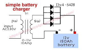
The presented circuit diagram acts as 12v battery charger.   We get 10 Amp current from the output of this charger which is suitable for charging 150Ah battery.  A 0-12 10 Amp stepdown transformer has been used in this, in its output we get 12v 10Amp.  To convert 12v AC to DC, 4 diodes 5408 have been used in this circuit which are connected in parallel.   This charger is very suitable and simple and low cost charger to charge the battery.  This charger can be easily made at home.  

basic audio amplifier circuit diagram

Image
The presented circuit diagram acts as an audio amplifier.  This is a basic simple audio amplifier circuit diagram.  With this circuit, very low power audio signals can be made more powerful.   In this 2 transistor BC 547 has been used.  And with this, 2 resistors R1, R2 and two capacitors C1, C2 have been used in this  circuit.  Basic audio amplifier circuit diagram  How to work basic audio amplifier   Very low power input audio signal is applied through capacitor C1 to the base of transistor Q1.  Transistor Q1 amplifies the power of the audio signal which we get at the ammeter of the transistor.   The audio signal received from the ammeter of transistor Q1 is applied to the base of transistor Q2 through capacitor C2.  And the transistor Q2 makes the audio signal more powerful than what we get on the transistor's collector.   We can hear them by connecting an 8 ohm speaker to the collector of transistor Q2.  You can enjoy

alcohol detector circuit diagram

Image
The presented circuit diagram serves as an alcohol detector.  This project is used to measure the level of alcohol in the breath.   Driving under the influence of alcohol causes accidents every day.  Very useful project to check whether driver is drunk or not.  This project is very cheap and easy to use.   In this project, we have used the MQ3 sensor to detect the level of alcohol in the breath.  An IC LM3914 is used to convert the alcohol sensor output to digital.  And pins 1, 18, 17, 16, 15, 14, 13, 12, 11 and 10 of ic LM3914 are output pins.  These pins are connected to 10 different LEDs of different colors.  Pin 5 of the ic is connected to the output pin of the alcohol sensor.  And the pin 3 and 9 of the ic is connected to +v.  And pins 2 and 4 of ic are grounded. Circuit diagram  How to work alcohol detector  As soon as an alcoholic exhales in front of the MQ3 sensor, +V starts getting at the output pin 5 of the sensor.  And the output pi