Posts

Showing posts from January, 2022

what is resistor

Image
 register is an electrical component used to reduce the electrical current in a circuit. The register is measured in units of ohms and has two terminals.  The register is constructed using carbon or metal wire. There are mainly two types of registers, fixed value registers, variable registers.  Fixed value resistors,  The value of fixed value register is always fixed, its value cannot be increased or decreased whereas the value of variable register can be increased or decreased.  Resistor Color Code Calculator Resistor Color Code Calculator Select the colors of the bands on your resistor: Band 1: Black Brown Red Yellow Green Blue Violet Grey White Band 2: Black Brown Red Oregon Yellow Green Blue Violet Grey White Band 3:
what is diode

Image
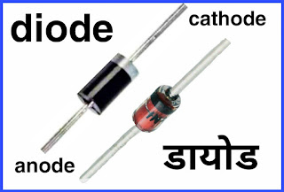
  Diode  Diode is an electrical component. Its full name is Semiconductor Diode Valve. The diode was discovered in the 19th century by a scientist named Thomas Edison.  Diodes are made of germanic silicon semiconductor. There are many types of diodes, but most of them have two ends, one anode and the other cathode.  Speciality  The main feature of diodes is that they allow current to flow in only one direction with low resistance. While they do not allow the electric current to flow in the opposite direction, due to this feature, they convert AC (alternating current) to DC (direct current).  Watch video  Main work  Diode is the most commonly used electrical component. Diodes are mainly used to convert AC current into DC current. Apart from this, diodes are used in battery chargers, inverters and all electrical equipment running on DC current. Symbol  The diagram below shows the symbol used in the circuit diagram of a

rf remote control circuit diagram

Image
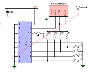
 Presented circuit diagram is of RF remote control switch.  This remote control switch allows up to four electrical appliances to be turned on and off.   The biggest feature of the RF remote control switch is that it does not traditionally require the remote to be placed in front of the appliance to turn it on or off as it works on RF frequency. The radio frequency ranges from 30 KHz to 300 MHz. RF module ASK modulation is used in this system.  ASK modulation (Aptitude Shift Keying).  Radio frequency remote is better than ir remote because the range of RF remote is much better than ir remote.  The range of RF remote is about 30 to 100 meters. You can use this remote from any corner of the house.  With this remote control, you can turn on/off electrical appliances from any corner of the house.   This project is divided into two section transmitter circuit and receiver circuit.   Rf transmitter circuit  The RF remote control transmitter secti

led bulb driver circuit diagram

Image
      Illuminating the Future:  Understanding LED Bulb Driver Circuit Diagrams Introduction In today's world, the lighting industry is undergoing a significant transformation with the widespread adoption of LED (Light Emitting Diode) technology. LED bulbs are energy-efficient, long-lasting, and environmentally friendly alternatives to traditional incandescent and fluorescent lighting. However, behind the simplicity of an LED bulb lies a complex LED driver circuit that plays a crucial role in ensuring optimal performance. In this blog post, we'll delve into the world of LED bulb driver circuit diagrams, demystifying their components and functionality to help you better understand these modern marvels. **Chapter 1: The Basics of LED Technology** Before we dive into LED driver circuit diagrams, let's establish a fundamental understanding of LED technology. LEDs are semiconductor devices that emit light when an electric current passes through

wireless current transmission

Image
The presented circuit works to transfer electricity from one place to another without wires.  In this project there are two coils made of copper wire, one coil acts as transmitter and the other coil acts as receiver.  This is a very efficient structure used for magnetic induction. The circuit diagram of wireless current transmission is given below. In It uses a coil made from 100 turns of copper wire on a PVC pipe and a transistor BD139 is also used in this circuit.   Pin 1 of the coil used in the transmitter circuit is connected to the base of the transistor BD139 through a 10K ohm resistor and pin 3 of the coil is connected to the collector of the transistor.  Pin 2 of the coil (which happens after 50 turns) is connected to +9v. Wireless current transmission circuit diagram  This wireless current transmission circuit converts DC current into high frequency AC current and generates a magneti