Posts

Showing posts from January, 2021

12 volt DC regulated power supply circuit diagram

Image
 The presented circuit diagram is of a 12 volt DC regulated power supply. This circuit is built using ic 7812.  Two capacitors c1 (4700uf 50V) and capacitor c2 (1UF) have been used in this circuit to filter the voltage.  By giving 110 volt to 230 volt AC to the input of the presented circuit, its output provides 12 volts DC regulated power supply.  You can use this power supply in any 12v DC powered device. This power supply is absolutely safe.
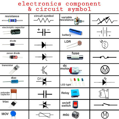
electronic components circuit symbol

Image
    Understanding Electronic Component Circuit Symbols Introduction Electronic circuits are the building blocks of modern technology. From smartphones to spacecraft, electronic circuits power and control a wide range of devices. To work with these circuits effectively, engineers and enthusiasts alike need to understand the symbols used to represent electronic components in circuit diagrams. In this blog post, we will delve into the world of electronic component circuit symbols, demystifying the key symbols you need to know.   Chart of electronics components circuit symbol  Resistors Resistors are one of the fundamental components in electronics. They limit the flow of current in a circuit. In circuit diagrams, resistors are represented by a zigzag line. The symbol is simple, resembling a serpentine path. The value of the resistance is often indicated next to the symbol in ohms (Ω). Capacitors Capacitors store electrical charge and release it when needed. They are repres

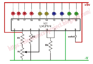
battery level indicator circuit diagram using ic LM3914

Image
  Battery level indicator circuit  Due to excessive discharge, there is often a possibility of the battery getting damaged soon.  Here we need to pay attention to the charging level of the battery.   For this, the battery level indicator can prove to be a great project because with the battery level indicator project, we can easily know the information about the charging level of the battery and the battery can be saved from damage in time.   The Battery Charging Level Indicator is a project that will monitor the charging status of the battery at all times and notify you. The presented circuit diagram acts as a battery level indicator . Through this circuit, you can find out the charging level of any battery. This circuit is built using ic LM3914. Battery level indicator circuit diagram  This battery level indicator is very low cost and easy to use. The circuit requires 9 to 12 volts DC to function. The list of electrical components used in

9v dc regulated power supply circuit diagram

Image
  9v DC regulated power supply circuit diagram  The presented circuit diagram is of a 9 volt DC regulated power supply.  This circuit is built using ic 7809.  Two capacitors c1 4700uf 50V and capacitor c3 1UF have been used in this circuit to filter the voltage.     By giving 110 volt to 230 volt AC to the input of the presented circuit, its output provides 9 volts DC regulated power supply.  You can use this power supply in any 9v DC powered device.  This power supply is absolutely safe.

ac 230v to dc 9v 500mA converter circuit diagram

Image
 The presented circuit diagram is used to convert ac 220 volts to DC 9 volts 500mA .  A 9 0 9v 500mA transformer is used in this circuit.   In the primary winding of the transformer, Ac is given 230 volts and its secondary windings gives 9V Ac.  Two diodes 1N4007 have been used in this circuit to convert AC voltage to DC voltage.  And a capacitor 2200uf have been used to filter the DC voltage.

what is relay

Image
Understanding Relays: The Hidden Heroes of Electrical Control Introduction Relays might not be as flashy as the latest gadgets or as prominent as smartphones, but they play a crucial role in our daily lives. These unassuming devices are the unsung heroes of electrical control, allowing us to automate, control, and safeguard various processes. In this blog post, we'll dive deep into the world of relays, exploring what they are, how they work, and their numerous applications. What is a Relay? A relay is an electromechanical device that acts as a switch controlled by an electrical signal. It consists of three main components: 1. **Coil**: The coil is an electromagnetic winding made of wire, which generates a magnetic field when current flows through it. 2. **Contacts**: The contacts are the actual switches inside the relay, and they are typically made of metal. These contacts open or close in response t

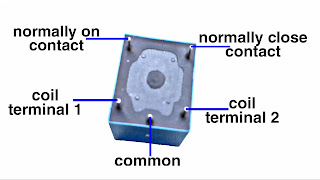
relay pinout

Image
PCB mountable relay pinout  Standard relay pinout