Posts

Showing posts from 2020

sound operator on off switch circuit diagram

Image
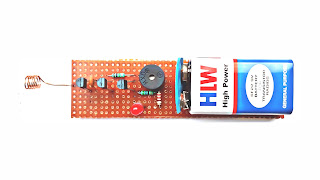
 The presented circuit acts as a clap switch.  This circuit can be turned on or off by any voice.   This circuit is built using IC CD4017.Also, three transistor BC547 have also been used in this circuit.   Any electrical device can be turned on or off by connecting a relay to this circuit.   This circuit requires 9V DC current to work.  You can also supply power to this circuit from a 9V battery or a 9 0 9 V transformer.  list of all the electrical components used in this circuit is given below. Electronics components list  IC CD 4017 Transistor  Q1, Q2, Q3 BC 547 Resistor  R1, R2  10k ohm R2  1M ohm R4 470 ohm R5 1I ohm Capacitor  C1 103pf Diode  D1 1N4007  LED  Mic Relay  12v PCB BORD  How to make sound operator switch watch full video 

9v dc to 1.5v dc converter circuit diagram

Image
 The presented circuit is designed to convert 9 volts DC to 1.5 volts DC.  This circuit is built using transistor BC548 .   Two resistance 33k ohm and 10k ohm have been used in this circuit for voltage balancing.   You can connect a wall clock or any electrical device running 1.5V with this circuit.

simple transformerless RGB LED lights glow power supply circuit diagram

Image
Simple transformerless RGB LED glow power supply   The presented project circuit diagram is a simple transformer-less power supply. Through this power supply you can glow 20 to 100 RGB LED lights.  This circuit is made using two polyester capacitors 474 J and 104 J.  We have used 4 diode 1N 4007 in this circuit to convert AC current to DC carrunt.   The list of electrical components use in this circuit have given below. List of electronics components  Capacitor  C1 474j 250v  C2 104j 400v  C3 47uf 160v Resistance  R1 1m ohm R2 22 ohm 1w Diode  1N4007 ×4

Sound detector switch circuit diagram

Image
Sound detector switch    The presented circuit serves as the sound detector sensor.  This circuit is built using timer ic 555.   Sound detector switch circuit diagram  This circuit is turned on by any sound.  And automatically turns off after a few seconds.  The list of electrical components used in this circuit is given below. Electronics components list  ic NE555  Transistor  Q1, Q2, Q3 BC 547 Resistance  R1, 4.7Ik ohm R2, 1k ohm R3, 470 ohm R4, 47k ohm R5, 330 ohm Capacitor C1, C2, 0.1ufC3, 100uf          Mic condenser  Diode  D1, 1N4007  Relay 12v PCB BORD 

LED bulb simple driver circuit diagram

Image
LED bulb driver  The circuit presented is for the driver of 7 and 9 watt LED bulbs.  This circuit is designed using a 105J capacitor.   And a capacitor 474J has also been used to control the voltage of the circuit.  And one capacitor 47UF is used in this circuit to filter the voltage.   4 diodes 1N4OO7 have been used in this circuit to convert ac voltage to DC voltage.  A mov has also been used to protect the circuit.   The list of electrical components used in this circuit is given below. LED bulb driver circuit diagram    Electronics components list  Capacitor  C1 105j 400v C2 474j 250v C3 47uf 160v Resistance  R1 1m ohm Diode  1n4007 ×4 MOV 270V PCB BORD

fan regulator circuit diagram

Image
Fan regulator  The circuit presented serves as the fan's regulator. BT136 is used in this circuit. And to control the fan speed, a variable register 220k ohm has been used in this circuit. The list of electrical components used in this circuit is given below. Fan regulator circuit diagram  Electronics components list  Triac BT136  diac (DB3 C312) Resistance  R1 10k ohm V/R1 220k ohm  Capacitor  C1 104 I 400v

remote control switch circuit diagram

Image
Remote control switch  The circuit presented serves as a remote control switch.  This circuit is built using ic CD 4017.  A 12 volt relay is used in this circuit which acts as a switch.   by this switch you can on or oof fan, cooler, bulb and any electricity device. list of all the electrical components used in this circuit  given below. Remote control switch circuit diagram  Electronics Components list  ic CD4017  Capacitor  1uf 25v ir receiver  TSOP 1738 Transistor  Q1 bc 557 Q2 BC547  Resistance  R1 10k ohm R2 100k ohm R3 1k ohm Diode  1N4007  Relay 12v PCB BOARD  Watch full video 

water level indicator circuit diagram

Image
Water level indicator  A Lifesaver at Your Fingertips: The Importance of a Water Level Indicator" Introduction Water is one of our planet's most precious resources. From quenching our thirst to powering industries, agriculture, and sustaining aquatic ecosystems, its significance cannot be overstated. However, in a world facing increasing water scarcity and pollution, managing this resource efficiently is paramount. One crucial tool that can help individuals, industries, and communities do just that is the Water Level Indicator. In this blog post, we'll delve into the importance of this simple yet invaluable device, exploring its benefits, applications, and why every responsible water user should consider installing one. Understanding Water Level Indicators A Water Level Indicator is a device designed to measure and display the level of water

Simple led bulb driver circuit diagram

Image
LED bulb driver circuit diagram    The presented circuit is designed for the driver of the LED bulb.  This circuit is built using 3 capacitors C 1, C 2, C 3.  A list of all the components used in this circuit is given below. Components list  C1, C2 105J 400V C3 47uf 160V Resistance  R1  1M ohm Diode  1N4007 ×4 PCB board 

wireless current detector circuit diagram

Image
Wireless current detector  The presented circuit is constructed using 3 NPN transistor BC547 .  With this circuit, you can check the electrical line of your house very easily.  And Pawar consumption is also very low in this circuit.    A small battery of 9 V is used to provide a power supply to this circuit.  And the list of electrical components used in this circuit is given below. Wireless current detector circuit diagram  Electronics components list  Transistor  BC547 ×3P 104 pf  Resistance  R1 1M ohm R2 220 ohm  R3 56 ohm  Coil Buzzer 3v LED LIGHT 9V battery connector  PCB BOARD  Battery 9V How to make wireless current detector watch full video