Password lock circuit diagram
Building a Secure Password Lock Circuit with IC CD4017: A Step-by-Step Guide
Introduction:
In today's digital age, security is of utmost importance. Whether it's your home, office, or personal belongings, safeguarding them with a reliable locking mechanism is essential. One effective way to enhance security is by creating a password-protected lock circuit. In this blog post, we will guide you through the process of building a secure password lock circuit using the versatile IC CD4017.

**Table of Contents:**
1. **What is IC CD4017?**
2. **Components Required**
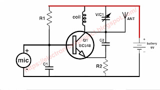
3. **Circuit Diagram**
4. **Circuit Explanation**
5. **Construction Steps**
6. **Testing the Password Lock Circuit**
7. **Enhancements and Customizations**
8. **Conclusion**
**1. What is IC CD4017?**
IC CD4017, also known as the Decade Counter, is a versatile CMOS-based integrated circuit. It's widely used in various electronic projects due to its ability to count and divide input clock signals. In our password lock circuit, we will utilize this IC to create a simple yet effective security system.
**2. Components Required**
Before we dive into building the circuit, let's gather the necessary components:
Power supply (5V)

**4. Circuit Explanation**
The password lock circuit diagram consists of a 4-digit keypad made up of four push-button switches (S1, S2, S3, S4) and an IC CD4017 connected to 10 LEDs (D1 to D10). Here's how it works:
- The push-button switches are connected to the clock (Pin 14) and reset (Pin 15) inputs of the CD4017.
- When you press a button, it triggers a clock pulse to the CD4017, causing it to increment its count.
- The CD4017 has 10 output pins (Q0 to Q9), which change their state sequentially with each clock pulse.
- Each output pin is connected to an LED through a resistor. When an output pin goes high, the corresponding LED lights up, indicating the current digit of the password.
- The CD4017 is set to reset after the 4th count (Q3) using the reset pin, ensuring that only a 4-digit password is accepted.
**5. Construction Steps**
Now, let's build the password lock circuit step by step:
Step 1: Place the IC CD4017 on the breadboard or PCB.
Step 2: Connect the clock (Pin 14) and reset (Pin 15) inputs to the push-button switches (S1 to S4).
Step 3: Connect the LEDs (D1 to D4) to the first four output pins (Q0 to Q3) of the CD4017, using the appropriate resistors in series.
Step 4: Connect the LEDs (D5 to D8) to the remaining output pins (Q4 to Q7) of the CD4017, using the appropriate resistors.
Step 5: Connect the reset (RST) pin of the CD4017 to the GND (ground) pin to ensure a 4-digit password.
Step 6: Connect the power supply (5V) and ground (GND) to the circuit.
Step 7: Your password lock circuit is now complete!
**6. Testing the Password Lock Circuit**
To test your newly built password lock circuit:
1. Power up the circuit with 5V.
2. Press the push-button switches (S1 to S4) in the correct sequence to enter your 4-digit password.
3. As you press each button, the corresponding LED should light up.
4. If you enter the correct password, all four LEDs should be lit consecutively, indicating success.
5. If the password is incorrect, press the reset button (S4) to start over.
**7. Enhancements and Customizations**
You can enhance and customize this password lock circuit in several ways:
- Use a relay to control an external locking mechanism (e.g., a door lock or safe).
- Add more LEDs and push-button switches to create a longer or more complex password.
- Incorporate a timer circuit to trigger an alarm or lockout period after multiple incorrect attempts.
- Implement a microcontroller for more advanced features and remote access.
**8. Conclusion**
In this blog post, we've learned how to build a simple yet effective password lock circuit using IC CD4017. This DIY project can enhance the security of your personal belongings or add an extra layer of protection to your projects. Remember to customize and expand upon this basic design to suit your specific security needs. Stay safe and enjoy your newfound knowledge of electronics and security systems!
How to make password lock switch watch full video


Comments