electronic components circuit symbol
Understanding Electronic Component Circuit Symbols
Introduction
Electronic circuits are the building blocks of modern technology. From smartphones to spacecraft, electronic circuits power and control a wide range of devices. To work with these circuits effectively, engineers and enthusiasts alike need to understand the symbols used to represent electronic components in circuit diagrams. In this blog post, we will delve into the world of electronic component circuit symbols, demystifying the key symbols you need to know.
Chart of electronics components circuit symbol

Resistors
Resistors are one of the fundamental components in electronics. They limit the flow of current in a circuit. In circuit diagrams, resistors are represented by a zigzag line. The symbol is simple, resembling a serpentine path. The value of the resistance is often indicated next to the symbol in ohms (Ω).
Capacitors
Capacitors store electrical charge and release it when needed. They are represented in circuit diagrams by two parallel lines. The curved lines in proximity to one another indicate the plates of the capacitor, while the gap between them signifies the dielectric material between the plates.
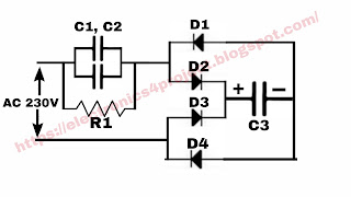
Diodes
Diodes allow current to flow in one direction while blocking it in the other. Their circuit symbol resembles an arrow pointing in the direction of allowable current flow. The triangle shape of the arrowhead indicates the diode's one-way nature.
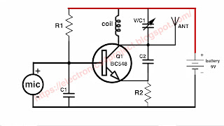
Transistors
Transistors are crucial for amplification and switching in electronic circuits. They come in various types, such as NPN and PNP bipolar junction transistors (BJTs) or N-channel and P-channel field-effect transistors (FETs). The symbols for these transistors differ slightly, but they all convey the same basic information - the flow of current through the device.
Inductors
Inductors store energy in a magnetic field when current flows through them. In circuit diagrams, inductors are represented by a series of coils. The number of coils and their proximity to each other can vary, indicating different inductance values.
Integrated Circuits (ICs)
Integrated circuits, also known as ICs or chips, contain numerous electronic components on a single semiconductor substrate. Their symbols typically depict the outline of the chip with various pins extending from it. Each pin has a specific function, and the datasheet for the IC provides details on their functions.
Conclusion
Understanding electronic component circuit symbols is essential for anyone working with electronics. These symbols serve as a universal language for engineers, hobbyists, and technicians to communicate complex circuit designs efficiently. While we've covered some of the most common symbols in this post, there are many more specialized symbols for specific components and functions.
As you delve deeper into the world of electronics, you'll encounter additional symbols and learn their meanings. So, whether you're designing your first circuit or troubleshooting a complex system, a solid grasp of electronic component circuit symbols is a valuable skill that will serve you well in your electronic endeavors.


Comments
Thanks for sharing this blog. this blog is very useful. I would like to suggest some other HRS Connectors