fm transmitter circuit diagram
Building Your Own FM Transmitter:
A Step-by-Step Guide
Introduction:
In an era where wireless communication is king, understanding the basics
of radio frequency (RF) technology can be both fascinating and practical.
One exciting project to delve into this world is building your own FM
transmitter. In this blog post, we'll provide you with a comprehensive
guide, including a circuit diagram, to create your very own FM
transmitter. Whether you're an electronics enthusiast or just curious
about how it works, this DIY project is both educational and fun.
**Chapter 1: Understanding the Basics of FM Transmitters**
Before we dive into the circuit diagram and assembly, let's briefly
explore what an FM transmitter is and how it works.
1. **What is an FM Transmitter?**
An FM transmitter is a device that can convert an audio
signal into a radio frequency signal for wireless transmission. In simple
terms, it allows you to broadcast your audio to nearby FM radios.
2. **How Does it Work?**
FM (Frequency Modulation) is a method of encoding information
on a carrier wave by varying its frequency. In an FM transmitter, your
audio signal modulates the frequency of the carrier wave, creating a
signal that can be received and played back by FM radios.
**Chapter 2: Components You'll Need**
Before we jump into building the circuit, let's gather the components
required for this project:
1. **NPN transistorBC548:** You'll need a dedicated FM transmitter
transistor like the transistor BC548 which simplifies the process.
2. **Capacitors:** Typically, you'll need a few ceramic and electrolytic
capacitors to stabilize the circuit.
3. **Inductors:** These are essential for filtering and tuning the
frequency.
4. **Resistors:** For voltage division and biasing.
5. **Microphone:** To capture the audio signal you want to transmit.
6. **Antenna:** A simple wire antenna is sufficient for short-range
broadcasting.
7. **Battery or Power Supply:** To provide power to the circuit.
8. **Breadboard or PCB:** Depending on your preference, you can assemble
the circuit on a breadboard for prototyping or create a PCB for a more
permanent setup.
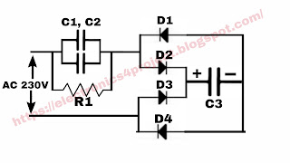
**Chapter 3: The FM Transmitter Circuit Diagram**

The circuit diagram illustrates a basic FM transmitter using the BC548 as
an example. Here's a brief overview of the key components:
- **Microphone:** Captures the audio input.
- **Crystal Oscillator:** Provides the stable frequency reference.
- **Phase-Locked Loop (PLL):** Modulates the carrier frequency with the
audio signal.
- **Antenna:** Transmits the modulated FM signal.
**Chapter 4: Assembling and Testing**
1. **Assemble the Circuit:** Follow the circuit diagram carefully,
connecting each component as shown. Double-check your connections to
ensure accuracy.
2. **Power Up:** Connect the power supply or battery to your circuit and
turn it on.
3. **Audio Input:** Connect an audio source (e.g., your smartphone or an
external microphone) to the microphone input of the transmitter.
4. **Tuning:** Use the inductors and capacitors to tune the transmitter to
your desired frequency. You can use an FM radio to find the clearest
available frequency in your area.
5. **Testing:** Turn on an FM radio, tune it to your transmitter's
frequency, and listen for the audio signal. You should hear the audio
you've input.
**Chapter 5: Enhancements and Considerations**
While the basic circuit outlined here is suitable for short-range
applications, there are various enhancements and considerations to
explore:
- **Range Extension:** You can improve the transmitter's range by adding a
more efficient antenna or amplification stages.
- **Audio Quality:** Experiment with different microphones and audio
sources to enhance the audio quality of your broadcast.
- **Regulatory Compliance:** Be aware of your country's regulations
regarding FM transmitters. Operating on certain frequencies or with
excessive power may require a license.
**Conclusion: Unlocking the World of FM Transmitters**
Building your own FM transmitter is not only a fascinating electronics
project but also a great way to gain a deeper understanding of RF
technology. As you explore this world, you'll discover various ways to
improve and expand your transmitter's capabilities.
Remember, this project is intended for educational purposes and
short-range personal use. Always comply with local regulations when
operating any RF device, and have fun exploring the exciting world of FM
transmitters!
Transistor
Q1 BC548
Resistance
R1 4.7k ohm
R2 330 ohm
Capacitor
C1 102pf
C2 47pf
परिवर्तनीय संधारित्र
C/R1 0 से 100pf
कुंडल 6टर्न
एमआईसी
एफएम ट्रांसमीटर कैसे बनाये


Comments
LO FELICITO AMIGO Y SALUDOS A TODA LA COMUNIDAD DE RF..
BYE FELIZ DIA TARDE Y NOCHE A TODOS...