wireless current transmission
The presented circuit works to transfer electricity from one place to another
without wires. In this project there are two coils made of copper wire,
one coil acts as transmitter and the other coil acts as receiver. This is
a very efficient structure used for magnetic induction.


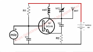
The circuit diagram of wireless current transmission is given below. In It
uses a coil made from 100 turns of copper wire on a PVC pipe and a
transistor BD139 is also used in this circuit.
Pin 1 of the coil used in the transmitter circuit is connected to the base
of the transistor BD139 through a 10K ohm resistor and pin 3 of the coil is
connected to the collector of the transistor. Pin 2 of the coil (which
happens after 50 turns) is connected to +9v.
Wireless current transmission circuit diagram
This wireless current transmission circuit converts DC current into high
frequency AC current and generates a magnetic field around.
wireless current receiver
When the receiver coil is placed in a magnetic field, current is generated
in it and the LED connected to the receiver coil starts flashing as shown in
the figure below.
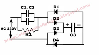
In the below circuit diagram, both the transmitter and receiver coils are
shown together.
The receiver coil has about 50 turns of 22 gauge wire.


Comments