wireless ac current detector circuit diagram
There is often a risk of injury due to electric shock during the repair of power lines and electrical equipment. This Wireless AC Current Detector is a very useful project to ensure the presence of electricity before repairing the power line and any electrical equipment.
This project is made using very few electrical components. this project made have been used two NPN transistor Q1, Q2 C1815 only and one LED. With this wireless ac current detector, you can easily detect the electric current flowing in any wire from a distance of about two to three inches without touching the wire.
Wireless ac current detector circuit diagram

This wireless current detector is very simple and low cost. With this wireless AC current detector, the electric current flowing through the wire can be easily detected without cutting the plastic.
Through this wireless AC current detector, neutral and phase (current wire)can be easily detected. When taken close to the neutral wire, the LED in it will not glow, while when taken near the phase(current) wire, the LED will glow.


This is a very suitable electrical project to find where electrical wires are broken inside plastic. Its use is very easy.
How to work, wireless ac current detector

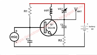
In this, a coil made of copper wire is used as an antenna which detects the electromagnetic induction flowing in any wire and sends a very low level signal to the base of transistor Q1.
And transistor Q1 converts the very low level signals received from the antenna into electric current and sends it to the base of transistor Q2, which causes transistor Q2 to turn on and the LED connected to its ammeter to glow.


Comments